Xiaomi Zigbee (3): Live Debugging
*
Preface
In our previous post, we explored the format of a JN516X firmware and its ISA (instruction set architecture), in preparation for further reverse engineering and vulnerability assessment of the device. In this final post of the series (for now), we will present a debugging harness made of a cheap JN5168 development board and a basic JTAG debugger. We will talk about the limitations of BA2 hardware debugging, and demonstrate a session with execution of arbitrary instructions (as well as an evaluation of the board state before and after the execution).
The Hardware
JN5169 Evaluation Kits are available from NXP. However, the kits are quite expensive (at $645 each). We wanted to make our research more approachable, and therefore, decided to look for cheaper alternatives. While it is possible to buy a single JN5168/JN5169 MCU at under $5, we had no intention of developing a PCB to host it (a lengthy and tedious endeavor, that requires intimate knowledge of the MCU). Luckily, SeeedStudio, a Chinese manufacturer of IoT boards for hobbyists, had exactly the device we needed: MeshBee, a JN5168-based programmable board. At $20, it’s considerably cheaper than the official evaluation kit from NXP (though it does require some additional hardware).
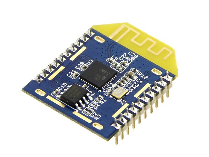 SeeedStudio MeshBee
As can be seen in MeshBee’s documentation, flashing MeshBee with a new firmware requires a programmer, and SeeedStudio provides one, called UartSBee v5. While it’s possible to flash the board directly using jenprog and a generic UART interface (see “Exploring the serial interface” in the first post in the series), we chose the convenience of a dedicated programmer. At $20, it wasn’t going to break the bank, and we were hoping it would help us debug the MCU, as well (as we figured out later, that wasn’t the case).
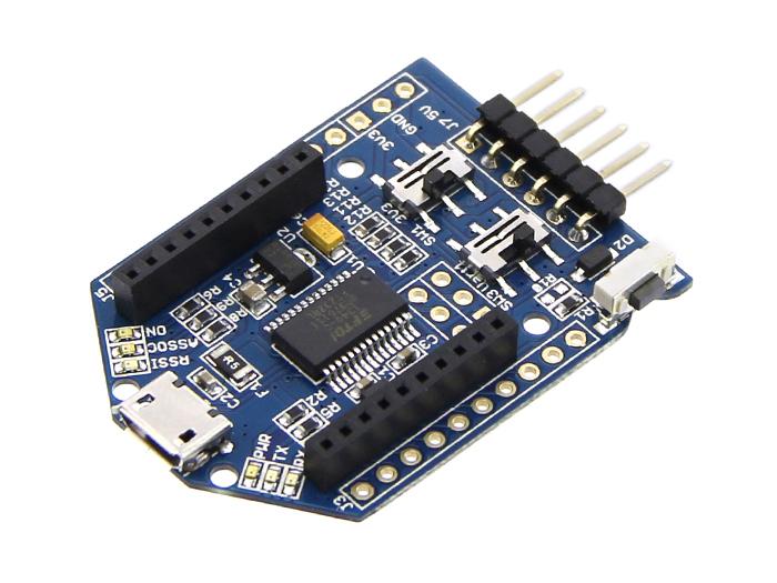 SeeedStudio UartSBee v5
Finally, we needed a JTAG debugger (we couldn’t know for sure that the UartSBee could be used as a debugger). There are many cheap JTAG debuggers, and we chose to work with TUMPA, a debugger we already had available to us. However, we are confident that any basic JTAG debugger, such as the BusPirate or the Xipiter Shikra would work just as well.
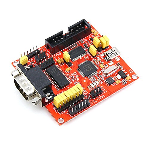 TIAO USB Multi Protocol Adapter (TUMPA)
Board Programming
Upon the arrival of the devices from SeeedStudio, we were able to hook them up to our development computer, and read the stock firmware both via JenProg and via BeyondStudio GUI. It’s always a good idea to back up the stock firmware:
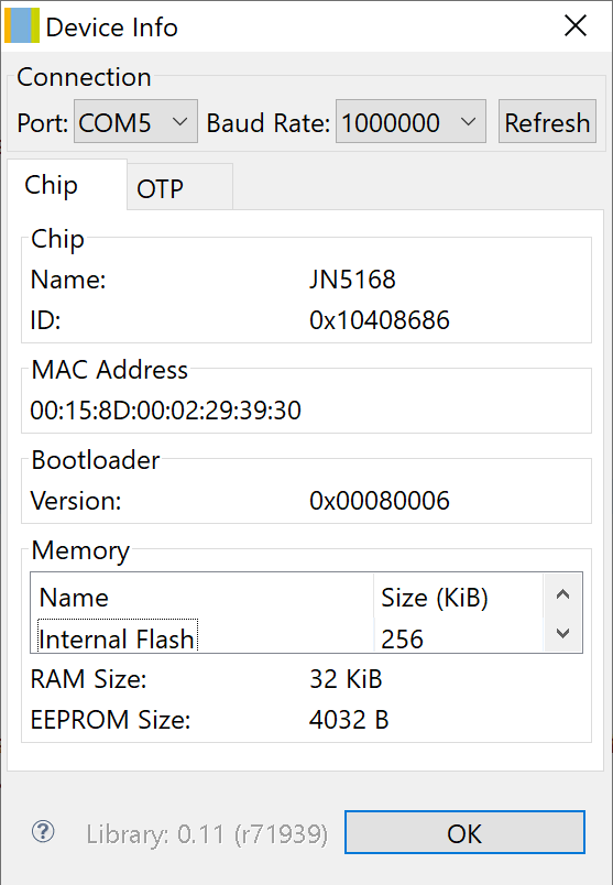 BeyondStudio: Device Info
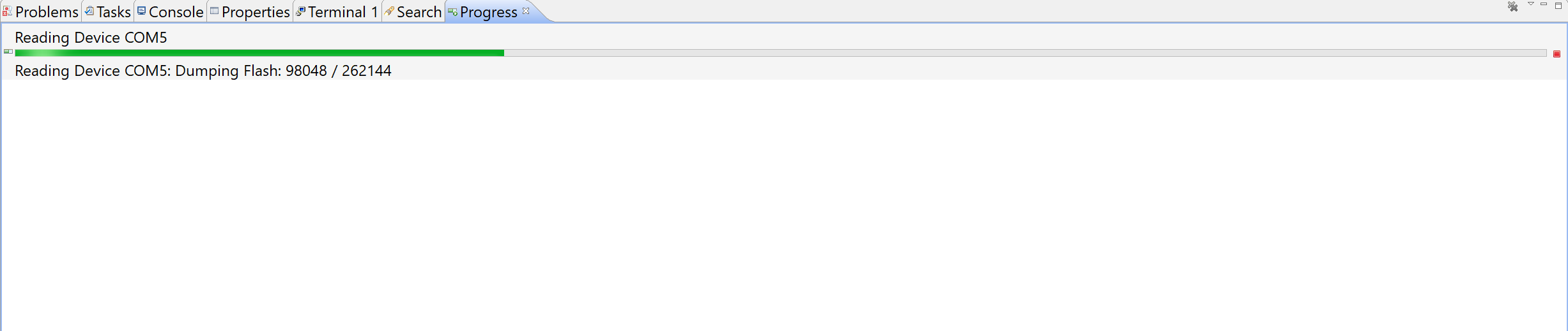 BeyondStudio: Reading Flash
Programming the device was equally easy. As mentioned in the previous post, we chose to work with JN-AN-1180 (available from NXP), and built the HomeSensorEndD project for JN5168:
06:11:45 **** Incremental Build of configuration AN1180_154_HomeSensorEndD for project JN-AN-1180-802-15-4-Home-Sensor-Demo ****
make clean JENNIC_CHIP=JN5168 all
for d in Build; do (cd $d; make  clean ); done
Building HW debug version ...
Building HW debug version ...
make[1]: Entering directory `/c/NXP/bstudio_nxp/workspace/JN-AN-1180-802-15-4-Home-Sensor-Demo/AN1180_154_HomeSensorEndD/Build'
rm -f AN1180_154_HomeSensorEndD.o AppQueueApi.o AN1180_154_HomeSensorEndD.d AppQueueApi.d
rm -f AN1180_154_HomeSensorEndD_JN5168_hwdbg.bin
rm -f AN1180_154_HomeSensorEndD_JN5168_hwdbg.elf
rm -f AN1180_154_HomeSensorEndD_JN5168_hwdbg.map
make[1]: Leaving directory `/c/NXP/bstudio_nxp/workspace/JN-AN-1180-802-15-4-Home-Sensor-Demo/AN1180_154_HomeSensorEndD/Build'
for d in Build; do (cd $d; make  all ); done
Building HW debug version ...
Building HW debug version ...
make[1]: Entering directory `/c/NXP/bstudio_nxp/workspace/JN-AN-1180-802-15-4-Home-Sensor-Demo/AN1180_154_HomeSensorEndD/Build'
rm -f AppQueueApi.o
rm -f AN1180_154_HomeSensorEndD.o
Compiling /c/NXP/bstudio_nxp/workspace/JN-AN-1180-802-15-4-Home-Sensor-Demo/AN1180_154_HomeSensorEndD/Source/AN1180_154_HomeSensorEndD.c ...
/c/NXP/bstudio_nxp/sdk/JN-SW-4163/../Tools/ba-elf-ba2-r36379/bin/ba-elf-gcc -c -o AN1180_154_HomeSensorEndD.o -DEMBEDDED -DJN516x=5160 -DJN5168=5168 -DJENNIC_CHIP_NAME=_JN5168 -DJENNIC_CHIP_FAMILY_NAME=_JN516x -march=ba2 -mcpu=jn51xx -mredzone-size=4 -mbranch-cost=3 -fomit-frame-pointer -O0 -fshort-enums -Wall  -Wpacked -Wcast-align -fdata-sections -ffunction-sections -g -DGDB -DUART1_DEBUG -DHWDEBUG -DWATCHDOG_ENABLED -DJENNIC_HW_BBC_RXINCCA=1 -DJENNIC_HW_BBC_DMA=1 -DJENNIC_HW_BBC_ISA=0 -DJENNIC_SW_EXTERNAL_FLASH=0 -DJN516X_DMA_UART_BACKWARDS_COMPATIBLE_API=1 -DUART_BACKWARDS_COMPATIBLE_API=1 -DJENNIC_CHIP=JN5168 -DJENNIC_CHIP_JN5168 -DJENNIC_CHIP_FAMILY=JN516x -DJENNIC_CHIP_FAMILY_JN516x -DJENNIC_STACK_MAC -DJENNIC_MAC_MAC -Wall -Wunreachable-code -DEMBEDDED -I/c/NXP/bstudio_nxp/sdk/JN-SW-4163/Platform/Common/Include -DJENNIC_PCB=DEVKIT4 -DJENNIC_PCB_DEVKIT4 -I/c/NXP/bstudio_nxp/sdk/JN-SW-4163/Platform/DK4/Include -I/c/NXP/bstudio_nxp/sdk/JN-SW-4163/Components/Common/Include -I/c/NXP/bstudio_nxp/workspace/JN-AN-1180-802-15-4-Home-Sensor-Demo/AN1180_154_HomeSensorEndD/Source -I/c/NXP/bstudio_nxp/workspace/JN-AN-1180-802-15-4-Home-Sensor-Demo/AN1180_154_HomeSensorEndD/Source/.. -I/c/NXP/bstudio_nxp/workspace/JN-AN-1180-802-15-4-Home-Sensor-Demo/Common/Source -I/c/NXP/bstudio_nxp/sdk/JN-SW-4163/Components/NXPLogo/Include -I/c/NXP/bstudio_nxp/sdk/JN-SW-4163/Components/Utilities/Include -I/c/NXP/bstudio_nxp/sdk/JN-SW-4163/Components/AppQueueApi/Include  -I/c/NXP/bstudio_nxp/sdk/JN-SW-4163/Components/AppApi/Include -I/c/NXP/bstudio_nxp/sdk/JN-SW-4163/Components/MAC/Include -I/c/NXP/bstudio_nxp/sdk/JN-SW-4163/Components/MMAC/Include -I/c/NXP/bstudio_nxp/sdk/JN-SW-4163/Components/HardwareApi/Include -I/c/NXP/bstudio_nxp/sdk/JN-SW-4163/Components/Aes/Include -I/c/NXP/bstudio_nxp/sdk/JN-SW-4163/Components/DBG/Include -I/c/NXP/bstudio_nxp/sdk/JN-SW-4163/Components/MAC/Include -I/c/NXP/bstudio_nxp/sdk/JN-SW-4163/Components/TimerServer/Include -I/c/NXP/bstudio_nxp/sdk/JN-SW-4163/Components/PDM/Include  /c/NXP/bstudio_nxp/workspace/JN-AN-1180-802-15-4-Home-Sensor-Demo/AN1180_154_HomeSensorEndD/Source/AN1180_154_HomeSensorEndD.c -MD -MF AN1180_154_HomeSensorEndD.d -MP

Compiling /c/NXP/bstudio_nxp/sdk/JN-SW-4163/Components/AppQueueApi/Source/AppQueueApi.c ...
/c/NXP/bstudio_nxp/sdk/JN-SW-4163/../Tools/ba-elf-ba2-r36379/bin/ba-elf-gcc -c -o AppQueueApi.o -DEMBEDDED -DJN516x=5160 -DJN5168=5168 -DJENNIC_CHIP_NAME=_JN5168 -DJENNIC_CHIP_FAMILY_NAME=_JN516x -march=ba2 -mcpu=jn51xx -mredzone-size=4 -mbranch-cost=3 -fomit-frame-pointer -O0 -fshort-enums -Wall  -Wpacked -Wcast-align -fdata-sections -ffunction-sections -g -DGDB -DUART1_DEBUG -DHWDEBUG -DWATCHDOG_ENABLED -DJENNIC_HW_BBC_RXINCCA=1 -DJENNIC_HW_BBC_DMA=1 -DJENNIC_HW_BBC_ISA=0 -DJENNIC_SW_EXTERNAL_FLASH=0 -DJN516X_DMA_UART_BACKWARDS_COMPATIBLE_API=1 -DUART_BACKWARDS_COMPATIBLE_API=1 -DJENNIC_CHIP=JN5168 -DJENNIC_CHIP_JN5168 -DJENNIC_CHIP_FAMILY=JN516x -DJENNIC_CHIP_FAMILY_JN516x -DJENNIC_STACK_MAC -DJENNIC_MAC_MAC -Wall -Wunreachable-code -DEMBEDDED -I/c/NXP/bstudio_nxp/sdk/JN-SW-4163/Platform/Common/Include -DJENNIC_PCB=DEVKIT4 -DJENNIC_PCB_DEVKIT4 -I/c/NXP/bstudio_nxp/sdk/JN-SW-4163/Platform/DK4/Include -I/c/NXP/bstudio_nxp/sdk/JN-SW-4163/Components/Common/Include -I/c/NXP/bstudio_nxp/workspace/JN-AN-1180-802-15-4-Home-Sensor-Demo/AN1180_154_HomeSensorEndD/Source -I/c/NXP/bstudio_nxp/workspace/JN-AN-1180-802-15-4-Home-Sensor-Demo/AN1180_154_HomeSensorEndD/Source/.. -I/c/NXP/bstudio_nxp/workspace/JN-AN-1180-802-15-4-Home-Sensor-Demo/Common/Source -I/c/NXP/bstudio_nxp/sdk/JN-SW-4163/Components/NXPLogo/Include -I/c/NXP/bstudio_nxp/sdk/JN-SW-4163/Components/Utilities/Include -I/c/NXP/bstudio_nxp/sdk/JN-SW-4163/Components/AppQueueApi/Include  -I/c/NXP/bstudio_nxp/sdk/JN-SW-4163/Components/AppApi/Include -I/c/NXP/bstudio_nxp/sdk/JN-SW-4163/Components/MAC/Include -I/c/NXP/bstudio_nxp/sdk/JN-SW-4163/Components/MMAC/Include -I/c/NXP/bstudio_nxp/sdk/JN-SW-4163/Components/HardwareApi/Include -I/c/NXP/bstudio_nxp/sdk/JN-SW-4163/Components/Aes/Include -I/c/NXP/bstudio_nxp/sdk/JN-SW-4163/Components/DBG/Include -I/c/NXP/bstudio_nxp/sdk/JN-SW-4163/Components/MAC/Include -I/c/NXP/bstudio_nxp/sdk/JN-SW-4163/Components/TimerServer/Include -I/c/NXP/bstudio_nxp/sdk/JN-SW-4163/Components/PDM/Include  /c/NXP/bstudio_nxp/sdk/JN-SW-4163/Components/AppQueueApi/Source/AppQueueApi.c -MD -MF AppQueueApi.d -MP

Linking AN1180_154_HomeSensorEndD_JN5168_hwdbg.elf ...
/c/NXP/bstudio_nxp/sdk/JN-SW-4163/../Tools/ba-elf-ba2-r36379/bin/ba-elf-gcc -Wl,--gc-sections -Wl,-u_AppColdStart -Wl,-u_AppWarmStart -TApp_Stack_Size.ld -march=ba2 -mcpu=jn51xx -mredzone-size=4 -mbranch-cost=3 -fomit-frame-pointer -O0 -fshort-enums -g -nostartfiles -L/c/NXP/bstudio_nxp/sdk/JN-SW-4163/Chip/JN5168/Build -L/c/NXP/bstudio_nxp/sdk/JN-SW-4163/Chip/JN5168/Library -Wl,--defsym,g_bSWConf_Debug=1 -Wl,-defsym,g_bSWConf_AltDebugPort=1 -L/c/NXP/bstudio_nxp/sdk/JN-SW-4163/Platform/DK4/Library -L/c/NXP/bstudio_nxp/sdk/JN-SW-4163/Components/Library -L/c/NXP/bstudio_nxp/sdk/JN-SW-4163/Stack/MAC/Build -TAppBuildMac.ld -o AN1180_154_HomeSensorEndD_JN5168_hwdbg.elf AN1180_154_HomeSensorEndD.o AppQueueApi.o -Wl,--start-group  -lAppApi_JN516x -lMAC_JN516x -lTimerServer_JN516x -lTOF_JN516x -lXcv_JN516x -lAes_JN516x -lHardwareApi_JN516x -lMicroSpecific_JN516x -lBoot_JN516x -lPDM_EEPROM_JN516x_NO_RTOS -lBoardLib_JN516x -Wl,--end-group -Wl,-Map,AN1180_154_HomeSensorEndD_JN5168_hwdbg.map
/c/NXP/bstudio_nxp/sdk/JN-SW-4163/../Tools/ba-elf-ba2-r36379/bin/ba-elf-size AN1180_154_HomeSensorEndD_JN5168_hwdbg.elf
   text	   data	    bss	    dec	    hex	filename
  32358	    148	   9515	  42021	   a425	AN1180_154_HomeSensorEndD_JN5168_hwdbg.elf

Generating binary ...
/c/NXP/bstudio_nxp/sdk/JN-SW-4163/../Tools/ba-elf-ba2-r36379/bin/ba-elf-objcopy -S -O binary AN1180_154_HomeSensorEndD_JN5168_hwdbg.elf AN1180_154_HomeSensorEndD_JN5168_hwdbg.bin
make[1]: Leaving directory `/c/NXP/bstudio_nxp/workspace/JN-AN-1180-802-15-4-Home-Sensor-Demo/AN1180_154_HomeSensorEndD/Build'

06:11:53 Build Finished (took 7s.813ms)
The build creates the binaries AN1180_154_HomeSensorEndD_JN5168_hwdbg.bin and AN1180_154_HomeSensorEndD_JN5168_hwdbg.elf. The first file is the firmware that has to be flashed onto the device (in our case, we flash it onto our MeshBee). The second file is an ELF object, that can be loaded by gdb and is used to debug the application.
Firmware Debugging
The previous step of building a sample firmware was important, as the process of debugging with the board was not yet clear to us. Therefore, we wanted to stick with the instructions provided by NXP as much as possible. For example, in the instructions, gdb requires an ELF file with symbols for successful debugging, and we obviously didn’t have that file for the Xiaomi firmware. Furthermore, building the project with debugging enabled produces a bigger binary. We couldn’t tell yet whether the differences (other than the “debugging enabled” bit in the header) were critical for successful debugging, or not. All in all, it was possible that gdb could successfully debug the Xiaomi firmware, were we just to change the “debugging enabled” bit in the header - but we wanted to have a working debugging setup before such experimentations.
So, with a sample firmware (with symbols) in hand, it was time to attempt a debugging session. Unfortunately, we quickly discovered that the UartSBee board was not suitable for debugging, and we had to look for a different solution. As an aside, the stock MeshBee firmware is used to run Arduino-based applications. We assume the UartSBee board can be used to debug those applications (by using custom interfaces provided by the stock firmware). However, since we were not interested in using the stock MeshBee firmware, we couldn’t rely on this kind of debugging, and headed in the direction of JTAG debugging.
Information about debugging a JN5168 chip is scarce. SeeedStudio, for example, provides no information in this regard - even though the MeshBee’s firmware is open-sourced and available on GitHub. NXP has some documentation on the matter of debugging, but it relates specifically to using the NXP Evaluation Kit (including the development board and a Jennic-branded JTAG debugger). While it was helpful in understanding some of the debugging processes, we had to find a different approach.
The software side of the debugging process is based on a combination of gdb (a version specific to BA2) and another program from the toolchain called jp3 (JTAG Proxy). jp3 is responsible for connecting to the MCU via a JTAG debugger, and exposing the debugging functionality to gdb. Attempts to run jp3 with the TUMPA connected resulted in failure:
C:\NXP\bstudio_nxp\sdk\Tools\ba-elf-ba2-r36379\bin>jp3.exe ftdi jtag://localhost:1234
jp3: JTAG protocol via USB/parallel port for Windows.
Version 1.6.3
Assuming debug_if's TAP has an IDCODE of 0x14951185.
Error: No supported ftdi based interfaces found!
It was clear that the program is looking for a specific JTAG adapter, and wasn’t programmed to work with the TUMPA. Could we find a way to add support for additional JTAG debuggers? In the beginning, we were working with the Windows binary jp3.exe that came with BeyondStudio, under the assumption that no source code fo the program was available. Debugging it revealed that jp3 was looking for a certain combination of FTDI device ID and description string. Following is the dump of the structure that lists the supported JTAG debuggers:
[0x004140c0]> pxr
0x004140c0 0x00000403  .... 1027
0x004140c4 0x00006010  .`.. 24592
0x004140c8 0x00415cb0  .\A. (.rdata) str.Beyond R 0x6f796542 (Beyond) -->  ascii ('B')
0x004140cc 0x00415cb7  .\A. (.rdata) str.Debug_Key R 0x75626544 (Debug Key) -->  ascii ('D')
0x004140d0 ... (null) ...
0x004140d8 0x00000403  .... 1027
0x004140dc 0x00006010  .`.. 24592
0x004140e0 0x00415cb0  .\A. (.rdata) str.Beyond R 0x6f796542 (Beyond) -->  ascii ('B')
0x004140e4 0x00415cc1  .\A. (.rdata) str.Debug_Hub R 0x75626544 (Debug Hub) -->  ascii ('D')
0x004140e8 0x00000001  .... 1
0x004140ec ... (null) ...
0x004140f0 0x00000403  .... 1027
0x004140f4 0x00006010  .`.. 24592
0x004140f8 0x00415cb0  .\A. (.rdata) str.Beyond R 0x6f796542 (Beyond) -->  ascii ('B')
0x004140fc 0x00415ccb  .\A. (.rdata) str.JTAG_Adapter R 0x4741544a (JTAG Adapter) -->  ascii ('J')
0x00414100 0x00000002  .... 2
0x00414104 ... (null) ...
0x00414108 0x00000403  .... 1027
0x0041410c 0x0000cff8  .... @hit1_0 53240
0x00414110 0x00415cd8  .\A. (.rdata) str.Amontec R 0x6e6f6d41 (Amontec) -->  ascii ('A')
0x00414114 ... (null) ...
0x00414118 0x00000004  .... 4
0x0041411c ... (null) ...
0x00414120 0x000015ba  .... 5562
0x00414124 0x0000002a  *... 42 ascii ('*')
0x00414128 ... (null) ...
0x00414130 0x00000005  .... 5
0x00414134 ... (null) ...
0x00414138 0x000015ba  .... 5562
0x0041413c 0x0000002b  +... 43 ascii ('+')
0x00414140 ... (null) ...
0x00414148 0x00000005  .... 5
0x0041414c ... (null) ...
0x00414150 0x000015ba  .... 5562
0x00414154 0x00000004  .... 4
0x00414158 ... (null) ...
0x00414160 0x00000005  .... 5
0x00414164 ... (null) ...
0x00414168 0x000015ba  .... 5562
0x0041416c 0x00000003  .... 3
0x00414170 ... (null) ...
0x00414178 0x00000005  .... 5
0x0041417c ... (null) ...
0x00414180 0x00000403  .... 1027
0x00414184 0x00006010  .`.. 24592
0x00414188 0x00415ce0  .\A. (.rdata) str.Digilent R 0x69676944 (Digilent) -->  ascii ('D')
0x0041418c 0x00415ce9  .\A. (.rdata) str.Digilent_Adept_USB_Device R 0x69676944 (Digilent Adept USB Device) -->  ascii ('D')
0x00414190 0x00000006  .... 6
0x00414194 ... (null) ...
0x00414198 0x00000403  .... 1027
0x0041419c 0x0000ac09  .... 44041
0x004141a0 0x00415d03  .]A. (.rdata) str.Atomic R 0x6d6f7441 (Atomic) -->  ascii ('A')
0x004141a4 ... (null) ...
0x004141a8 0x00000003  .... 3
0x004141ac ... (null) ...
0x004141b0 0x00000403  .... 1027
0x004141b4 0x00008220   ... 33312
0x004141b8 0x00415d0a  .]A. (.rdata) str.DISTORTEC R 0x54534944 (DISTORTEC) -->  ascii ('D')
0x004141bc 0x00415d14  .]A. (.rdata) str.JTAG_lock_pick_Tiny_2 R 0x4741544a (JTAG-lock-pick Tiny 2) -->  ascii ('J')
0x004141c0 0x00000007  .... 7
For each of the elements of the structure, there’s the USB ID pair (for example, for Beyond Debug Key it is 0x0403:6010 - meaning it’s based on an FTDI FT2232C/D/H), and the manufacturer and device name. By patching the program, we could make it work with arbitrary JTAG adapters (here, we replaced support for an Amontec JTAG debugger with support for the TUMPA):
[0x004140c0]> pxr
[...]
0x00414108 0x00000403  .... 1027
0x0041410c 0x00008a98  .... 35480
0x00414110 0x00415cd8  .\A. (.rdata) str.TIAO R 0x4f414954 (TIAO) -->  ascii ('T')
0x00414114 0x00415cdd  .\A. (.rdata) str.TIAO_USB_Multi_Protocol_Adapter R 0x4f414954 (TIAO USB Multi-Protocol Adapter) -->  ascii ('T')
0x00414118 0x00000004  .... 4
[...]
Later, however, we discovered the source of the program in the sources of the toolchain. It is, in fact, the project under the jtag directory. There, we could see the structure that we patched earlier (in the ftdi_driver.c file):
/* vendor, product, name pairs of supported devices */
struct ftdi_device_desc supported_devs[] = {
    { 0x0403, 0x6010, "Beyond", "Debug Key", l_beyond_debug_key_v1_2, 0 },          // Beyond Debug Key
    { 0x0403, 0x6010, "Beyond", "Debug Hub", l_beyond_debug_key_v1_1, 0 },          //   (eng. sample 2)
    { 0x0403, 0x6010, "Beyond", "JTAG Adapter", l_beyond_debug_key_v1_0, 0 },       //   (eng. sample 1)
    { 0x0403, 0xcff8, "Amontec", NULL, l_amontec_jtagkey2, 0 },                     // Amontec jtagkey/jtagkey2
    { 0x15ba, 0x002a, NULL, NULL, l_olimex_armusb, 0 },                             // Olimex arm-usb-tiny-h
    { 0x15ba, 0x002b, NULL, NULL, l_olimex_armusb, 0 },                             // Olimex arm-usb-ocd-h"
    { 0x15ba, 0x0004, NULL, NULL, l_olimex_armusb, 0 },                             // Olimex arm-usb-tiny"
    { 0x15ba, 0x0003, NULL, NULL, l_olimex_armusb, 0 },                             // Olimex arm-usb-ocd"
    { 0x0403, 0x6010, "Digilent", "Digilent Adept USB Device", l_digilent_hs1, 0 }, // Digilent hs1 ("adept")
    { 0x0403, 0xac09, "Atomic", NULL, l_amontec_jtagkey, 0 },                       // Atomic programming AP-114 (same layout as Amontec)
    { 0x0403, 0x8220, "DISTORTEC", "JTAG-lock-pick Tiny 2", l_lockpick2, 1 },       // JTAG-lock-pick Tiny 2
    { 0, 0 }
};
Adding support for arbitrary JTAG adapters was even easier now, and the added bonus of being able to run the JTAG proxy on Linux was the cherry on top. Compiling the toolchain for Linux, with a modern compiler, required some changes, and our changes are available as a fork. As part of the changes, we also updated the version of gdb to one that supports Python 3 (in order to use our analysis plugin).
With jp3 launching with TUMPA connected, the next step was to make the physical connection to the MCU’s JTAG pins. Here is a short description of the pins required for a daisy-chained JTAG debugging connection (for more detailed information, see “How JTAG works”):
TCK, Test Clock. This pin controls the clock (that synchronizes the rest of the JTAG signals), and is controlled by the debugger.TMS, Test Mode Select. JTAG, at its core, is a state machine, and this pin is used to control the state.TDI/TDO, Test Data In/Out. These pins are used to transfer data (such as JTAG commands) to the debugged chip, and to receive data back.TRST, Test Reset. This pin is used to reset the chip to a known state - however, it’s optional, not always present, and not necessary for JTAG operation (the reset can be performed in software, by holdingTMShigh for 5 clock cycles)
The aforementioned pins aren’t clearly marked, neither on the MeshBee (the development board), nor on the UartSBee (the programmer). Back in the description of the MCU’s pinout (see section “2.1 Pin Assignment” of the JN516X Datasheet, pp. 10-11), we saw that the JTAG pins (JTAG_TCK, JTAG_TMS, JTAG_TDO, JTAG_TDI) could either be on pins 26-29, or pins 36-38 and 40. It’s also apparent that pins 28-29 can be designated for UART0 (TXD0, RXD0), while pinss 38 and 40 can be treated both as UART0 and as UART1.
Based on the information above, our first and trivial attempt was to compile the project with debugging on UART0. The DEBUG_PORT variable in the Makefile was already set to the correct value, and all we had to do was enable debugging by uncommenting the DEBUG variable:
##############################################################################
# Debug options define DEBUG for HW debug
DEBUG ?=HW
#
#
# Define which UART to use for debug
DEBUG_PORT ?= UART0
Next, we looked up the UART0 connectors on the UartSBee board: those were marked CTS, RTS, TX0 and RX0 (note that there are no CTS1 and RTS1 on the MCU, and that must be the reason they are unnumbered on the board). As per the datasheet, CTS would match JTAG_TCK, RTS - JTAG_TMS, TX0 - JTAG_TDO, and RX0 - JTAG_TDI. With everything hooked up, and the board powered via 3v3, we were looking forward to our debugging session, only to see that it… did not work. jp3 could not identify the MCU via JTAG. Trying to identify the chip via OpenOCD failed, as well. What was wrong?
The hint came from looking at the pin labels of MeshBee (instead of those on UartSBee). On the MeshBee, the pins that we thought were CTS and RTS, were actually marked D12 and D13 - which means they were connected to pins 36 and 37 on the MCU. The TX0 and RX0 pins, on the other hand, were connected to pins 28-29 - because pins 38 and 40 were reserved for UART1. It meant that JTAG debugging of the MeshBee is only possible via UART1. We, therefore, updated the Makefile, and rebuilt the project:
##############################################################################
# Debug options define DEBUG for HW debug
DEBUG ?=HW
#
#
# Define which UART to use for debug
DEBUG_PORT ?= UART1
And connected the TUMPA to the MeshBee with the following pinout:
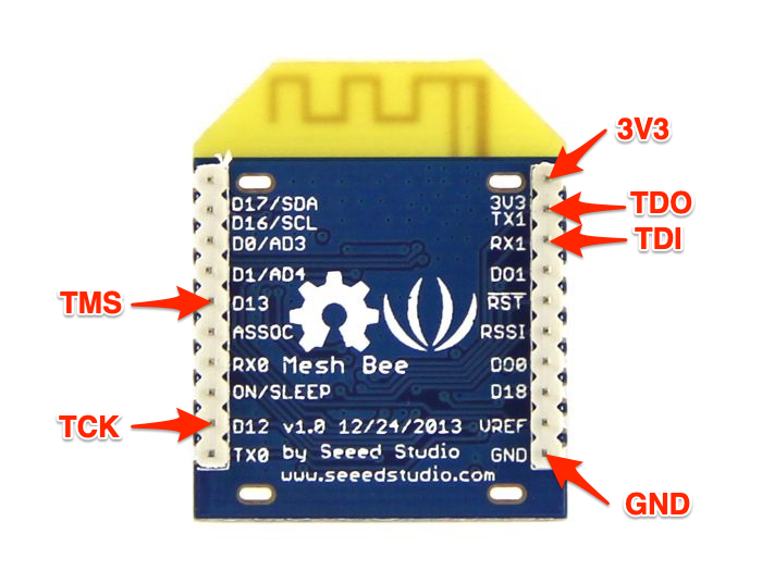 MeshBee: JTAG Pinout
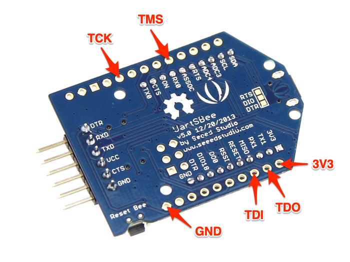 UartSBee: JTAG Pinout (with MeshBee on top)
At this point, jp3 successfully connected to the board:
❯ ./jp3 ftdi jtag://localhost:1234
jp3: JTAG protocol via USB/parallel port for linux.
Version 1.6.3
Assuming debug_if's TAP has an IDCODE of 0x14951185.
Using 'TIAO TIAO USB Multi-Protocol Adapter (TIM02108)' interface.
Enabling high speed ftdi mode.
Using JTAG clock of 15 MHz
Disabling UART not supported/required on this adapter.
JTAG chain length: 1
Found device 0 (IDCODE: 14951185) to have a debug_if connected to it
  Debug interfaces(s) detected: if3
  Using debug interface 3.
Processor version: BA22 v0.0.4
  Memory interface for debuggers: no
Remote ba debugging using jtag://localhost:1234
Press CTRL+c to exit.
And we could start debugging with gdb:
❯ ./ba-elf-gdb
GNU gdb (GDB) 7.6.2
Copyright (C) 2013 Free Software Foundation, Inc.
License GPLv3+: GNU GPL version 3 or later <http://gnu.org/licenses/gpl.html>
This is free software: you are free to change and redistribute it.
There is NO WARRANTY, to the extent permitted by law.  Type "show copying"
and "show warranty" for details.
This GDB was configured as "--host=x86_64-unknown-linux-gnu --target=ba-elf".
For bug reporting instructions, please see:
<http://www.gnu.org/software/gdb/bugs/>.
(gdb) target jtag jtag://localhost:1234
Remote ba debugging using jtag://localhost:1234
Using debug if3
Processor version: BA22 v0.0.4
Units present: PM PIC TICK_TIMER DEBUG 32GPR
4 hw watchpoints available.
0x0000032a in ?? ()
(gdb)
Notice: for those of you following this and attempting a debug session on your own, it’s worth noting that the JTAG debugging is not very reliable, and several attempts (including restarting the board) might be needed, before the CPU is successfully stalled and harnessed by gdb.
The executable section of the firmware is mapped as read-only by the bootloader. This prevents gdb from using software breakpoints (because debuggers internally implement software breakpoints by changing the executable memory to create a special exception/interrupt registered by the debugger, and then change it back to the original value when the breakpoint is reached). Therefore, the use of hardware breakpoints is necessary when debugging the MCU. There are 4 hardware breakpoints available, and they can be set using hbreak and thbreak commands in gdb. Furtheremore, stepping is supported - however, only stepping into (stepi) works: stepping out (until) and stepping over (nexti) are internally implemented by gdb via software breakpoints, and are not supported in our case.
Instruction reversing
The previous post outlined the work on reversing the ISA of JN516X and understanding the functionality of its instructions. However, that understanding is still incomplete: quite a few instructions are still a mistery to us, while a significant number of the known instructions has not been tested, and their exact behavior is just speculation. One of the goals of debugging a physical device is to test the behavior of instructions, in order to both verify our assumptions, and understand the instructions we haven’t yet figured out.
Since our plugin was written in Python, and we developed it in a way that its implementation was self-contained (i.e., not interwoven with radare2’s structure), it was possible to use it in gdb, as well. Thanks to it, it was possible to automate some of the tedious work required for reversing and verifying each instruction. Our test-on-board.py script (found in the pyba2 repository) implements the test-opcode command (available by sourcing the script from gdb). This command interoperates with gdb, in order to write the instruction (with procedurally generated arguments) to memory, execute it, and present the user with changes in the state of the registers. We hope to extend the script further, to support detection of memory changes, and to automatically infer the behavior of instructions based on the above changes.
Additional debugging options
Debugging the board with a specialized gdb and JTAG proxy is great, but what other options are there?
OpenOCD
OpenOCD (Open On-Chip Debugger) is an open-source utility for JTAG debugging. It supports a multitude of JTAG debuggers and target boards and architectures, but Beyond Architecture is not amongst them. OpenOCD can be extended to support additional architectures. This requires an implementation of a layer that translates debugging commands (such as accessing registers and memory), to low-level JTAG communications. Upon completing such an implementation, OpenOCD should be able to act as gdbserver for debugging JN516X MCUs (as a result, any debugger that supports BA2 and remote gdb connections, such as radare2, could be used). This can be an interesting project for the future, as the details of the implementation can be derived from reading the JTAG proxy source code.
radare2
radare2 supports 3rd party debuggers via plugins. Therefore, it should be possible to develop such a plugin (based in the source code of Beyond Architecture fork of gdb), that would work directly with JTAG proxy.
QEMU
We chose radare2 as our reverse engineering platform for researching the Xiaomi firmware due to a combination of its open-source nature (with good support for developing analysis plugins) and the emerging emulation feature (based on ESIL). The emulation feature should be useful in fuzzing the firmware effectively (for comparison, rebooting the physical board and reconnecting JTAG/gdb takes 5-10 seconds, making fuzzing extremely slow). However, while ESIL may be very effective in fuzzing small pieces of code, it may have difficulty handling emulation of a complete device. For that purpose, QEMU might be a better-suited candidate. By extending QEMU with BA2 support, it would be possible to research the firmware effectively and thoroughly.
Closing Remarks
This was a challenging project, that required a lot of trials and guesswork. Parts of the architecture remain obscure, and require further investigation. Thankfully, we were able to find some prior work (as well as some documentation and sources) that made our job easier. We think the work done so far is just a foundation, upon which further research can thrive. Feel free to share your thoughts in the comments section below, as well as in the GitHub repositories.